
Home > Directory of Drawing Lessons >Perspective Drawing > Guide to Drawing in Perspective
PERSPECTIVE DRAWING LESSONS : An Easy to Follow Guide Tutorial to Perspective Drawing for Beginners
|


|
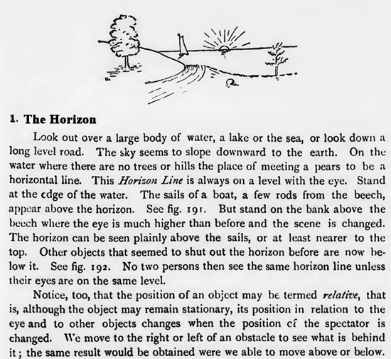
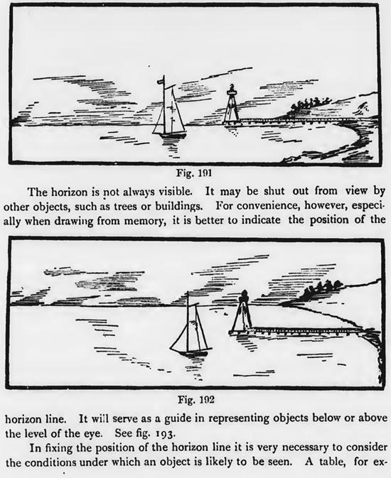
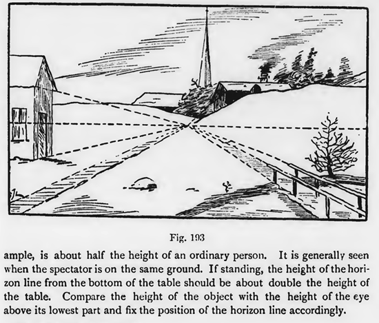
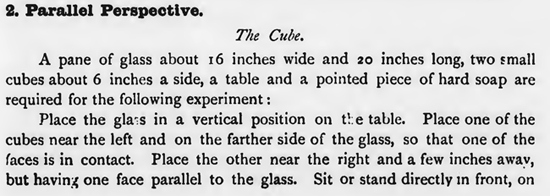
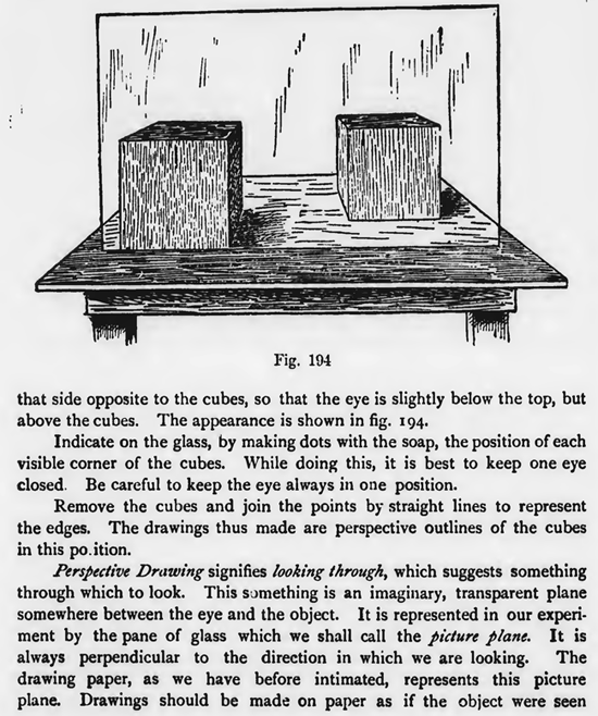
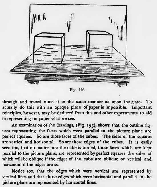
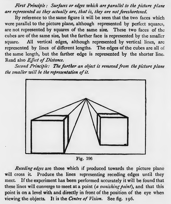
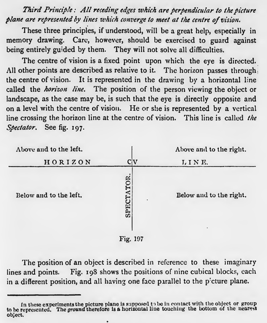
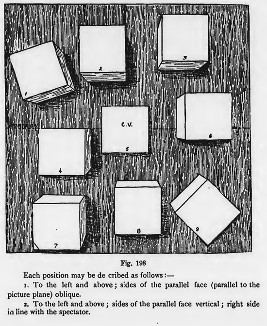
[The Text Above is Actually Images, so If You Need to Copy Text, You Can Do So Below] APPLIED PERSPECTIVE, GROUPING, SHADE AND SHADOWThe HorizonLook out over a large body of water, a lake or the sea, or look down a long level road. The sky seems to slope downward to the earth. On the water where there are no trees or hills the place of meeting a pears to be a horizontal line. This Horizon Line is always on a level with the eye. Stand at the edge of the water. The sails of a boat, a few rods from the beech, appear above the horizon. See fig. 191. But stand on the bank above the beech where the eye is much higher than before and the scene is changed. The horizon can be seen plainly above the sails, or at least nearer to the top. Other objects that seemed to shut out the horizon before are now below it. See fig. 192. No two persons then see the same horizon line unless their eyes are on the same level. Notice, too, that the position of an object may be termed relative, that is, although the object may remain stationary, its position in relation to the eye and to other objects changes when the position ef the spectator is changed. We move to the right or left of an obstacle to see what is behind it ; the same result would be obtained were we able to move above or below. The horizon is not always visible. It may be shut out from view by other objects, such as trees or buildings. For convenience, however, especially when drawing from memory, it is better to indicate the position of the horizon line. It will serve as a guide in representing objects below or above the level of the eye. See fig. 193. In fixing the position of the horizon line it is very necessary to consider the conditions under which an object is likely to be seen. A table, for example, is about half the height of an ordinary person. It is generally seen when the spectator is on the same ground. If standing, the height of the horizon line from the bottom of the table should be about double the height of the table. Compare the height of the object with the height of the eye above its lowest part and fix the position of the horizon line accordingly. Parallel Perspective.The Cube.A pane of glass about 16 inches wide and 20 inches long, two small cubes about 6 inches a side, a table and a pointed piece of hard soap are required for the following experiment : Indicate on the glass, by making dots with the soap, the position of each visible corner of the cubes. While doing this, it is best to keep one eye closed. Be careful to keep the eye always in one position. Remove the cubes and join the points by straight lines to represent the edges. The drawings thus made are perspective outlines of the cubes in this position. Perspective Drawing signifies looking through, which suggests something through which to look. This something is an imaginary, transparent plane somewhere between the eye and the object. It is represented in our experiment by the pane of glass which we shall call the picture plane. It is always perpendicular to the direction in which we are looking. The drawing paper, as we have before intimated, represents this picture plane. Drawings should be made on paper as if the object were seen through and traced upon it in the same manner as upon the glass. To actually do this with an opaque piece of paper is impossible. Important principles, however, may be deduced from this and other expertments to aid in representing on paper what we see. An examination of the drawings, (Fig. 195), shows that the outline figures representing the faces which were parallel to the picture plane are perfect squares. So are those faces of the cubes. The sides of the squares are vertical and horizontal. So are those edges of the cubes. It is easily seen too, that no matter how the cube is turned, those faces which are kept parallel to the picture plane, are represented by perfect squares the sides of which will be oblique if the edges of the cube are oblique or vertical and horizontal if the edges are so. Notice too, that the edges which were vertical are represented by vertical lines and that those edges which were horizontal and parallel to the picture plane are represented by horizontal lines. First Principle : Surfaces or edges which are parallel to the picture plane are represented as they actually are, that is, they are not foreshortened. By reference to the same figure it will be seen that the two faces which were parallel to the picture plane, although represented by perfect squares, are not represented by squares of the same size. These two faces of the cubes are of the same size, but the farther face is represented by the smaller square. All vertical edges, although represented by vertical lines, arc represented by lines of different lengths. The edges of the cubes are all of the same length, but the farther edge is represented by the shorter line. Second Principle: The farther an object is removed from the picture plane the smaller will be the representation of it. Receding edges are those which if produced towards the picture plane will cross it. Produce the lines representing receding edges until they meet. If the experiment has been performed accurately it will be found that these lines will converge to meet at a point (a vanishing point), and that this point is on a level with and directly in front of the position of the eye when viewing the objects. It is the Centre of Vision. See fig. 196. Third Principle : All receding edges which are perpendicular to Me picture plane are represented by lines which converge to meet at the centre of vision. These three principles, if understood, will be a great help, especially in memory drawing. Care, however, should be exercised to guard against being entirely guided by them. They will not solve all difficulties. The centre of vision is a fixed point upon which the eye is directed. All other points are described as relative to it. The horizon passes through the centre of vision. It is represented in the drawing by a horizontal line called the horizon line. The position of the person viewing the object or landscape, as the case may be, is such that the eye is directly opposite and on a level with the centre of vision. He or she is represented by a vertical line crossing the horizon line at the centre of vision. This line is called the Spectator. See fig. 197. The position of an object is described in reference to these imaginary lines and points. Fig. 198 shows the positions of nine cubical blocks, each in a different position, and all having one face parallel to the picture plane. In these experiments the picture plane is supposed tube in contact with the object or group to be represented. The ground therefore is a horizontal line touching the bottom of the nearest object. Each position may be described as follows :-1. To the left and above ; skies of the parallel face (parallel to the picture plane) oblique. Notice, in all these drawings, that there are but two classes of lines, representing two classes of edges :-
2. Receding edges, represented by lines which converge to meet in the centre of vision.
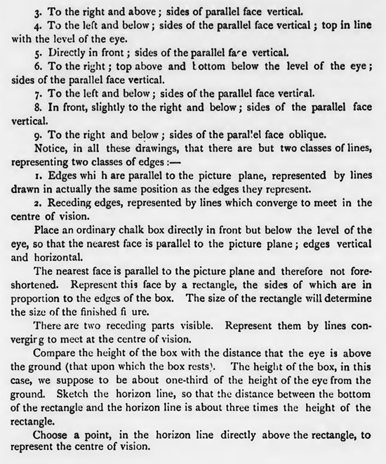
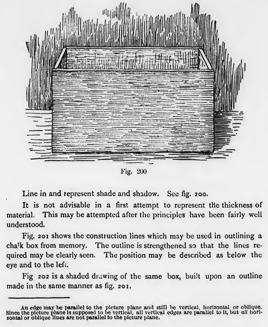
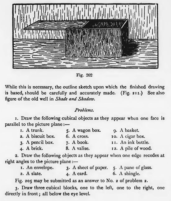
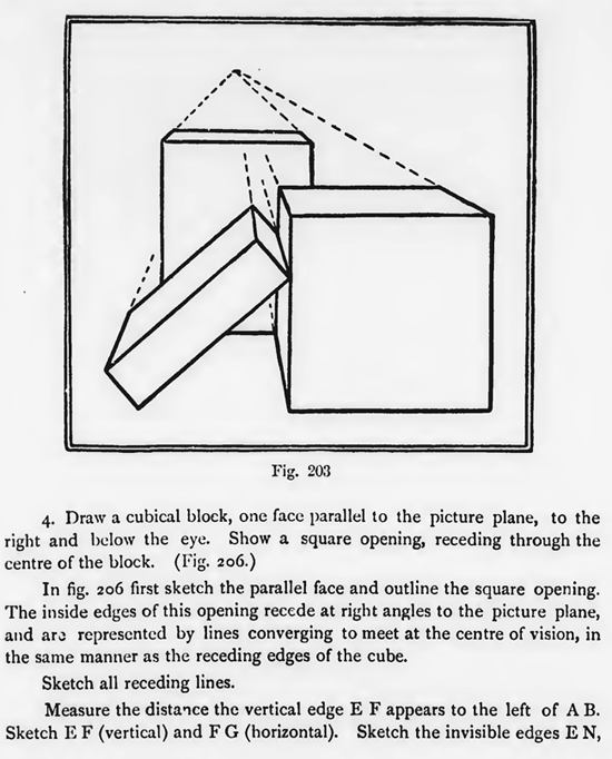
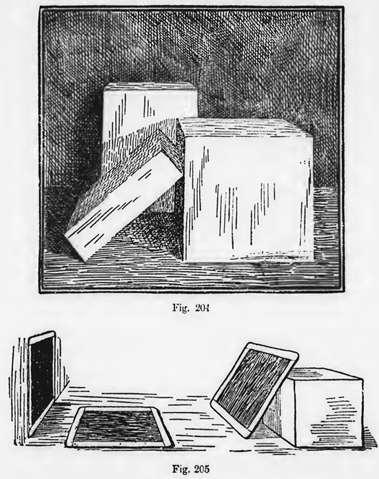
The nearest face is parallel to the picture plane and therefore not foreshortened. Represent this face by a rectangle, the sides of which are in proportion to the edges of the box. The size of the rectangle will determine the size of the finished figure. There are two receding parts visible. Represent them by lines convergir g to meet at the centre of vision. Compare the height of the box with the distance that the eye is above the ground (that upon which the box restsl. The height of the box, in this case, we suppose to be about one-third of the height of the eye from the ground. Sketch the horizon line, so that the distance between the bottom of the rectangle and the horizon line is about three times the height of the rectangle. Choose a point, in the horizon line directly above the rectangle, to represent the centre of vision. Compare the height of the farther visible edge with the height of the box and sketch a horizontal line in a corresponding position to represent the farther edge. This line is between the converging lines already drawn. The inside visible corners are vertical. Represent the visible parts by vertical lines. These vertical lines are between the horizontal lines representing the tops of the sides. Line in and represent shade and shadow. See fig. 200. It is not advisable in a first attempt to represent the thickness of material. This may be attempted after the principles have been fairly well understood. Fig. 201 shows the construction lines which may be used in outlining a chalk box from memory. The outline is strengthened so that the lines required may be clearly seen. The position may be described as below the eye and to the left. Fig 202 is a shaded dr.:wing of the same box, built upon an outline made in the same manner as fig. 201. An edge may be parallel to the picture plane and still be vertical. horizontal or oblique. Since the picture plane is supposed to be vertical, all vertical edges are parallel to it, but all horizontal or oblique lines are not parallel to the picture plane. Fig. 203 requires no explanation. The principles before stated are applied here as one face of each cubical block is parallel to the picture plane. Fig. 204 is a finished drawing of the same group. Although many objects are cubical in form, they do not possess the hard, exact outline of a cube. Care should be taken, in such cases, to I epresent such points of detail that will give the object a natural appearance. The square tablet is an excellent model to use In the first exercises of this section. Since it practically represents one surface of a cube, it may be used to advantage before drawing from the cube ass whole. It Is thought unnecessary to introduce it because of it being used in the section on Forshortening. While this is necessary, the outline sketch upon which the finished drawing is based, Could be carefully and accurately made. (Fig. 211) See also figure of the old well in Shade and Shadow. Problems.1 Draw the following cubical objects as they appear when one face is parallel to the picture plane 1. A trunk.
1.
An envelope.
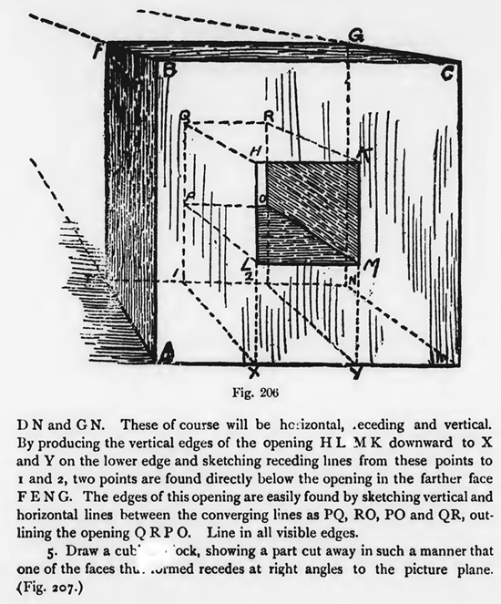
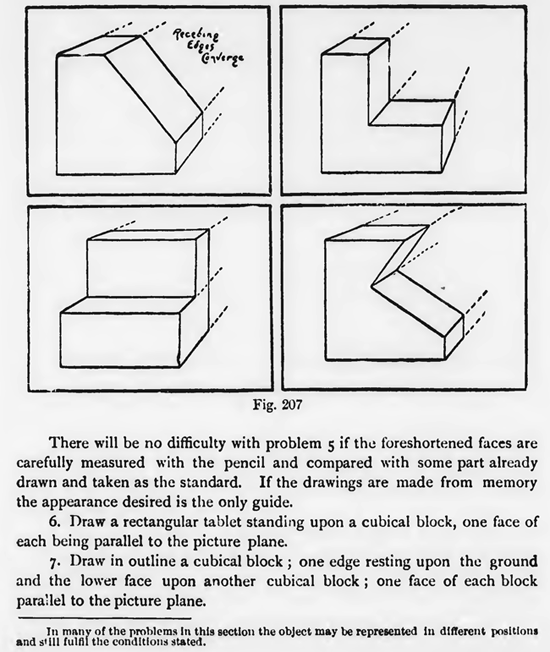
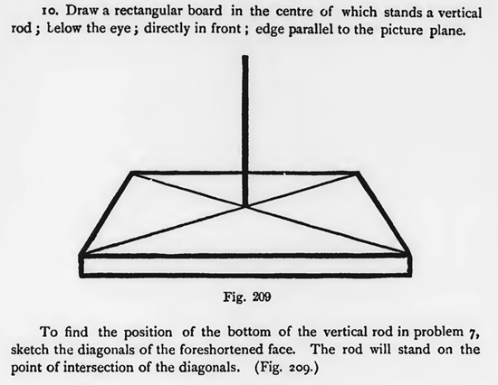
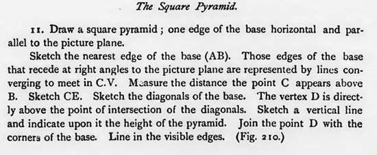
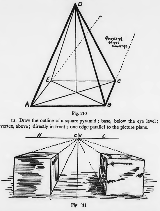
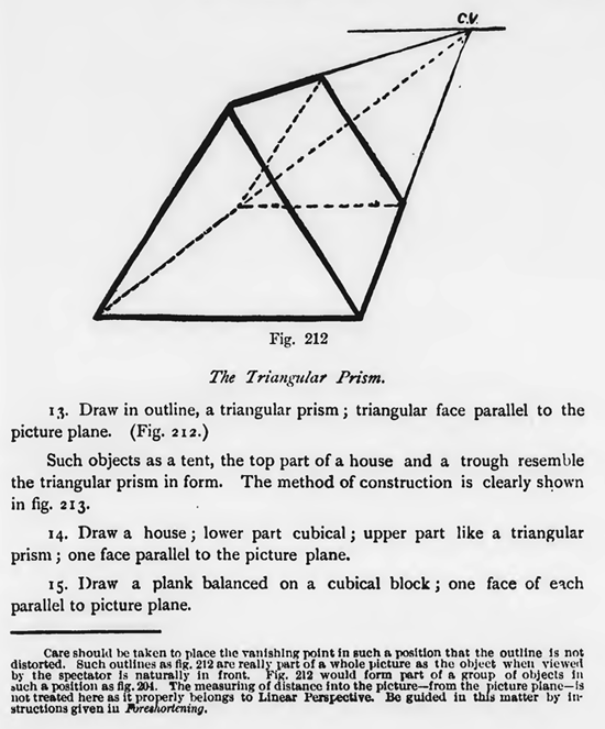
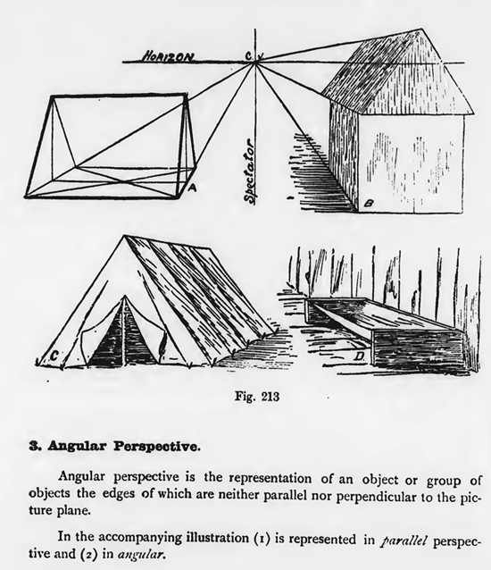
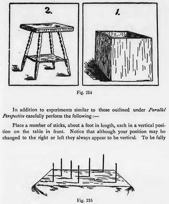
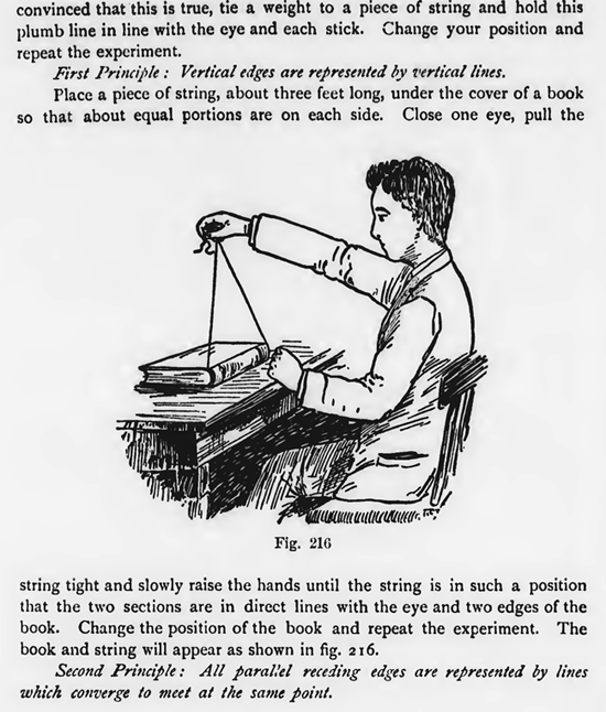
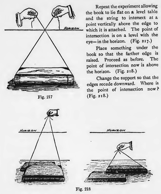
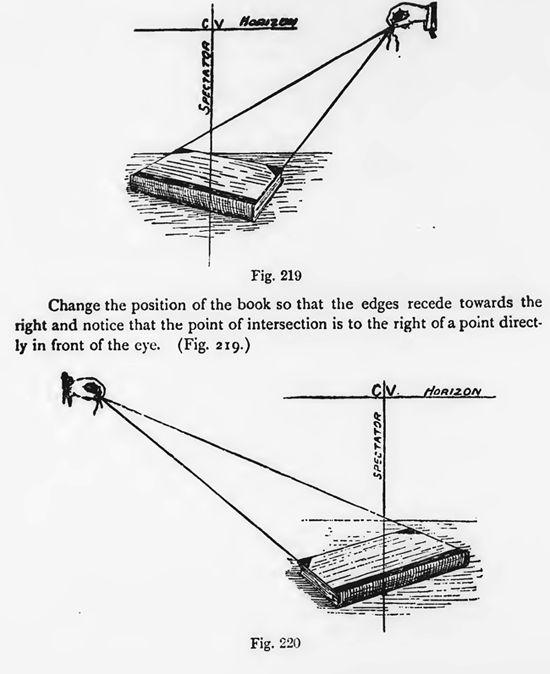
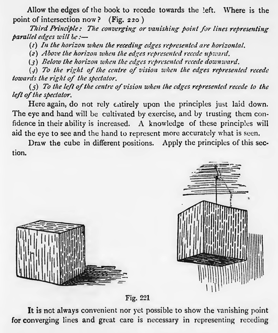
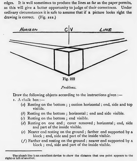
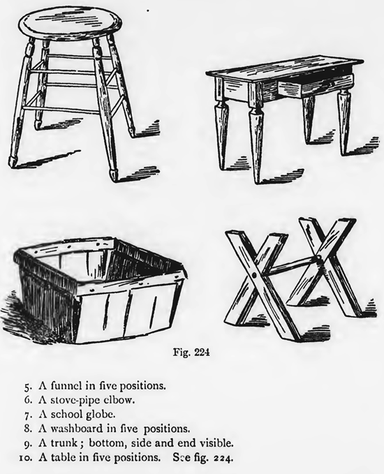
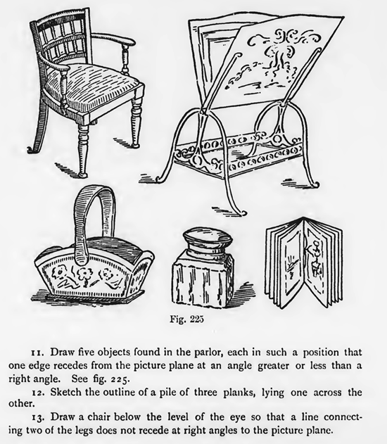
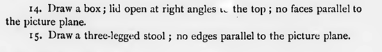
3. Draw three cubical blocks, one to the left, one to the right, one directly in front ; all below the eye level. 4. Draw a cubical block, one face parallel to the picture plane, to the right and below the eye. Show a square opening, receding through the centre of the block. (Fig. 206.) In fig. 206 first sketch the parallel face and outline the square opening. The inside edges of this opening recede at right angles to the picture plane, and arc represented by lines converging to meet at the centre of vision, in the same manner as the receding edges of the cube. Sketch all receding lines. Measure the distance the vertical edge E F appears to the left of A B. Sketch E F (vertical) and F G (horizontal). Sketch the invisible edges E N, D N and G N. These of course will be hc.izontal, seceding and vertical. By producing the vertical edges of the opening HL MK downward to X and Y on the lower edge and sketching receding lines from these points to and 2, two points are found directly below the opening in the farther face F E N G. The edges of this opening are easily found by sketching vertical and horizontal lines between the converging lines as PQ, RO, PO and QR, outlining the opening Q R P 0. Line in all visible edges. 5. Draw a cub' 'ock, showing a part cut away in such a manner that one of the faces that recedes at right angles to the picture plane. (Fig. 207.) There will be no difficulty with problem 5 if the foreshortened faces are carefully measured with the pencil and compared with some part already drawn and taken as the standard. If the drawings are made from memory the appearance desired is the only guide. 6. Draw a rectangular tablet standing upon a cubical block, one face of each being parallel to the picture plane. 7. Draw in outline a cubical block ; one edge resting upon the ground and the lower face upon another cubical block; one face of each block parallel to the picture plane. In many of the problems in this section the object may be represented in different positions and still fulfil the conditions stated. 8. Draw a book-shelf ; above the eye level. Show the thicknesss of the material. 9. Make an outline drawing of-an ordinary kitchen table; directly in front; side parallel to the picture plane; below the eye level. Fig. 208 shows the method of outlining a table in this position. 10. Draw a rectangular board in the centre of which stands a vertical rod ; Lelow the eye; directly in front ; edge parallel to the picture plane. To find the position of the bottom of the vertical rod in problem 7, sketch the diagonals of the foreshortened face. The rod will stand on the point of intersection of the diagonals. (Fig. 209.) The Square Pyramid.11. Draw a square pyramid ; one edge of the base horizontal and parallel to the picture plane. Sketch the nearest edge of the base (AB). Those edges of the base that recede at right angles to the picture plane are represented by lines converging to meet in C.V. Measure the distance the point C appears above B. Sketch CE. Sketch the diagonals of the base. 'The vertex D is direct. ly above the point of intersection of the diagonals. Sketch a vertical line and indicate upon it the height of the pyramid. Join the point D with the corners of the base. Line in the visible edges. (Fig. 210) 12. Draw the outline of a square pyramid ; base, below the eye level ; vertex, above ; directly in front ; one edge parallel to the picture plane. The Triangular Prism.13. Draw in outline, a triangular prism ; triangular face parallel to the picture plane. (Fig. 212.) Such objects as a tent, the top part of a house and a trough resemble the triangular prism in form. The method of construction is clearly shown in fig. 213. 14. Draw a house ; lower part cubical ; upper part like a triangular prism ; one face parallel to the picture plane. 15. Draw a plank balanced on a cubical block ; one face of etch parallel to picture plane. Care should be taken to place the vanishing point in such a position that the outline is not distorted. Such outlines as fig. 212 are really part of a whole picture as the object when viewed by the spectator is naturally in front. Fig. 212 would form part of a group of objects in such a position as flg. 204. The measuring of distance into the picture—from the picture plane—is not treated here as it properly belongs to Linear Perspective. Be guided iu this matter by instructions given iu Foreshortening. Angular Perspective.Angular perspective is the representation of an object or group of objects the edges of which are neither parallel nor perpendicular to the picture plane. In the accompanying illustration (1) is represented in larallel perspective and (2) in angular. In addition to experiments similar to those outlined under Parallel Perspective carefully perform the following :- Place a number of sticks, about a foot in length, each in a vertical position on the table in front. Notice that although your position may be changed to the right or left they always appear to be vertical. To be fully convinced that this is true, tie a weight to a piece of string and hold this plumb line in line with the eye and each stick. Change your position and repeat the experiment. First Principle : Vertical edges are represented by vertical fines. Place a piece of string, about three feet long, under the cover of a book so that about equal portions are on each side. Close one eye, pull the string tight and slowly raise the hands until the string is in such a position that the two sections are in direct lines with the eye and two edges of the book. Change the position of the book and repeat the experiment. The book and string will appear as shown in fig. 216. Second Principle : All parallel receding edges are represented by lines which converge to meet at the same point. Repeat the experiment allowing the book to lie flat on a level table and the string to intersect at a point vertically Change the support so that the edges recede downward. Where is the point of intersection now? (Fig. 218.) Change the position of the book so that the edges recede towards the right and notice that the point of intersection is to the right of a point directly in front of the eye. (Fig. 219.) Allow the edges of the book to recede towards the !eft. Where is the point of intersection now ? (Fig.220 ) Third Principle: The converging or vanishing point for lines representing parallel edges will be :— Here again, do not rely entirely upon the principles just laid down. The eye and hand will be cultivated by exercise, and by trusting them confidence in their ability is increased. A knowledge of these principles will aid the eye to see and the hand to represent more accurately what is seen. Draw the cube in different positions. Apply the principles of this section. It is not always convenient nor yet possible to show the vanishing point for converging lines and great care is necessary in representing receding edges. It is well sometimes to produce the lines as far as the paper permits, as this will give a better opportunity to judge of their correctness. Under ordinary circumstances it is safe to assume that if a picture looks right the drawing is correct. Problems.Draw the following objects according to the instructions given :1.A chalk box :- 2. A chair in five different positions. (Fig. 223.) 3. A cylinder lying on its curved surface. 4. A pen box in three positions. 5. A funnel in five positions. 6. A stove-pipe elbow. 7. A school globe. 8. A washboard in five positions. 9. A trunk ; bottom, side and end visible. 10. A table in five positions. See fig. 224. 11. Draw five objects found in the parlor, each in such a position that one edge recedes from the picture plane at an angle greater or less than a right angle. See fig. 225. 12. Sketch the outline of a pile of three planks, lying one across the other. 13. Draw a chair below the level of the eye so that a line connecting two of the legs does not recede at right angles to the picture plane. 14. Draw a box ; lid open at right angles the top ; no faces parallel to the picture plane. 15. Draw a three-legged stool ; no edges parallel to the picture plane. |


Privacy Policy ...... Contact Us