
Home > Directory of Drawing Lessons >Perspective Drawing > Perspective Drawing Tutorials
PERSPECTIVE DRAWING TUTORIALS : A Guide to Drawing in Perspective for Beginners
|


|
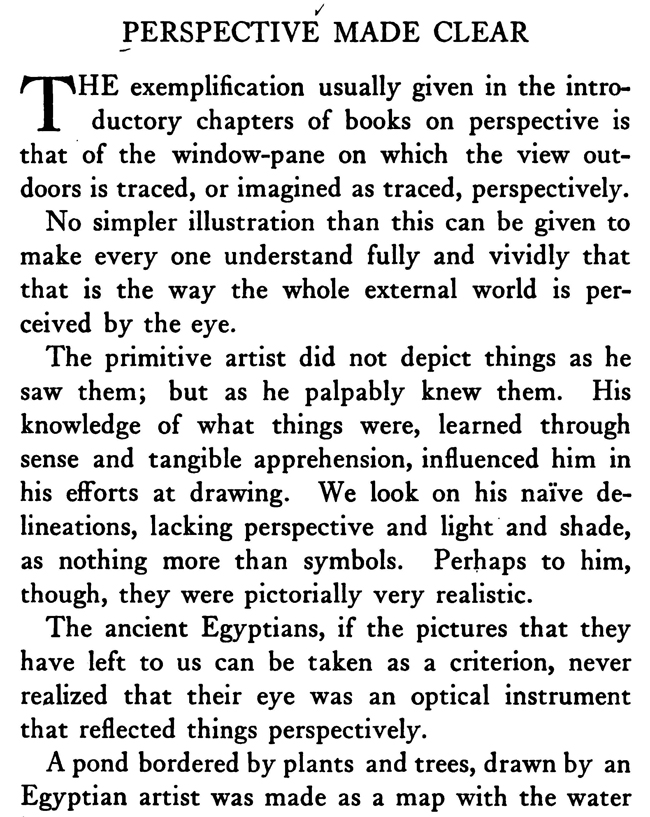
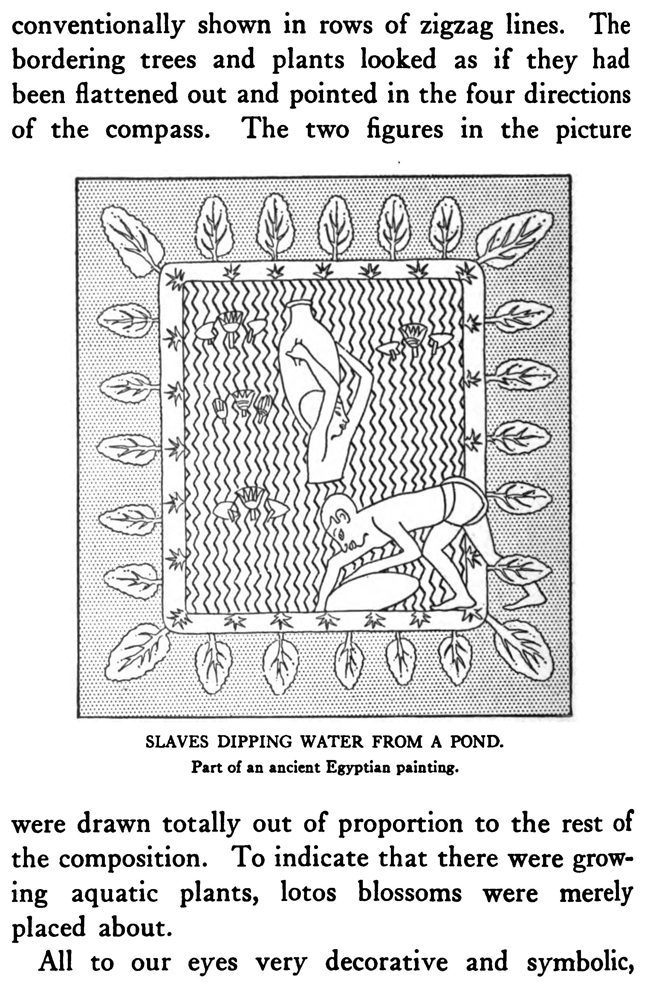
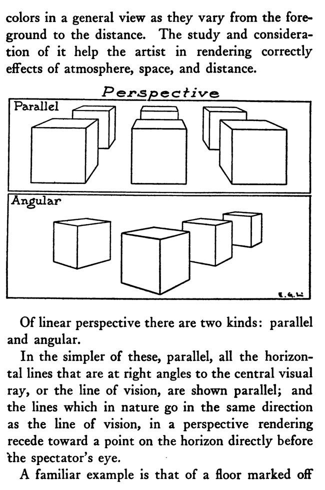
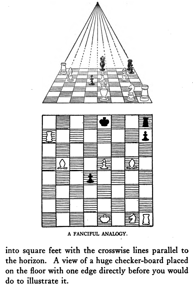
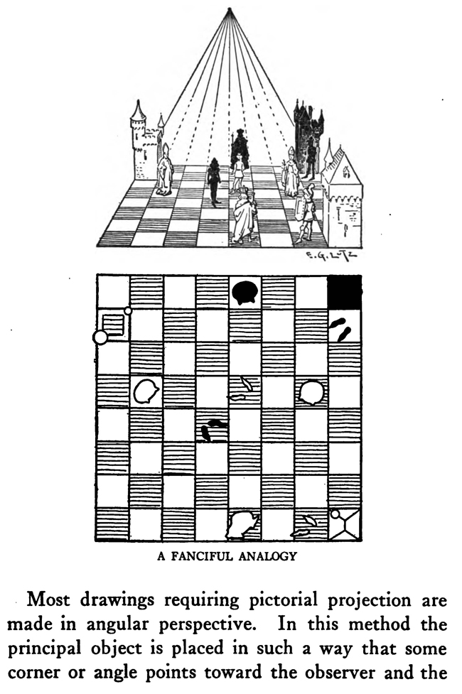
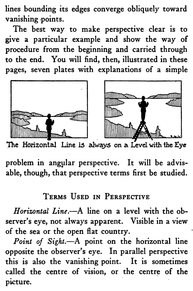
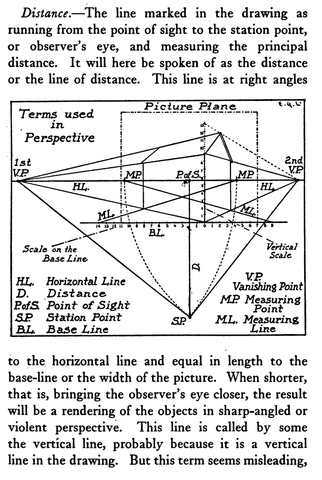
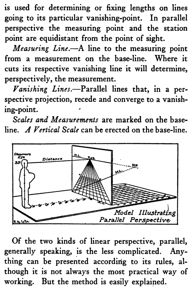
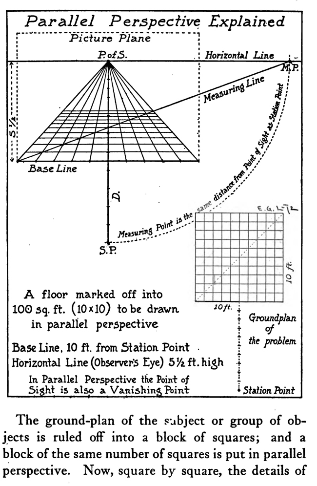
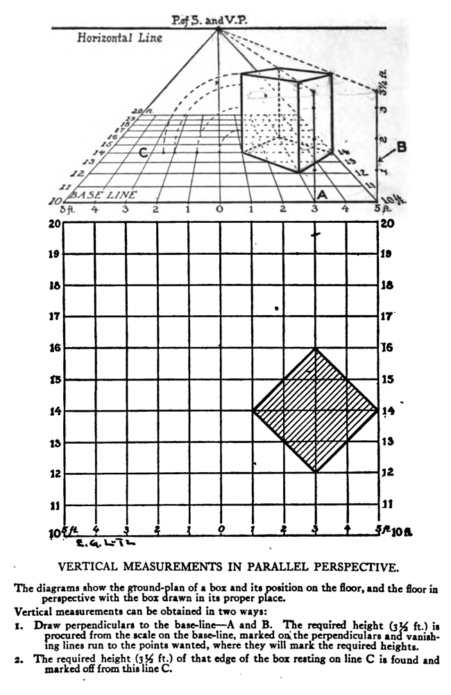
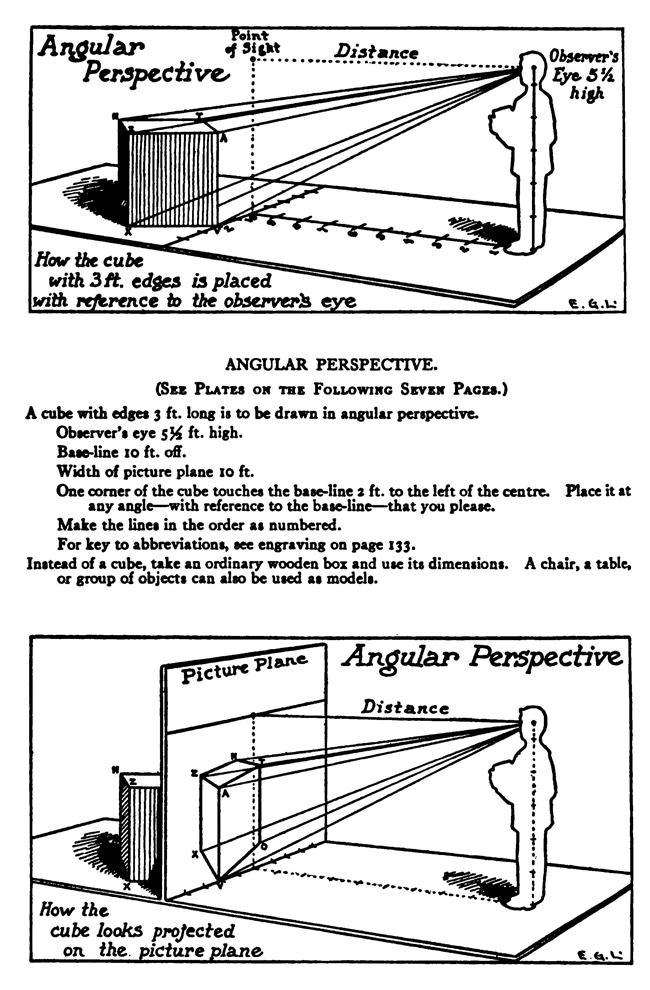
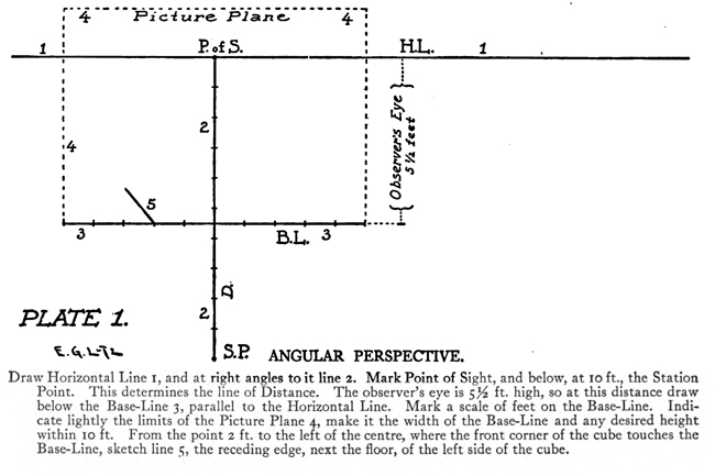
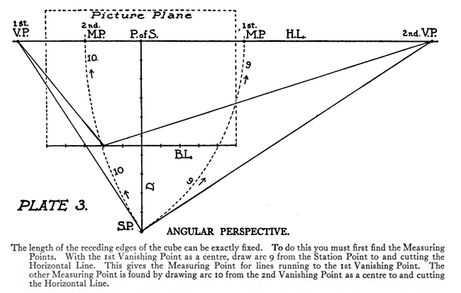
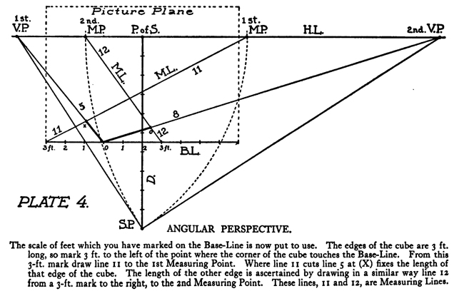
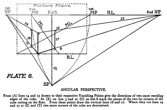
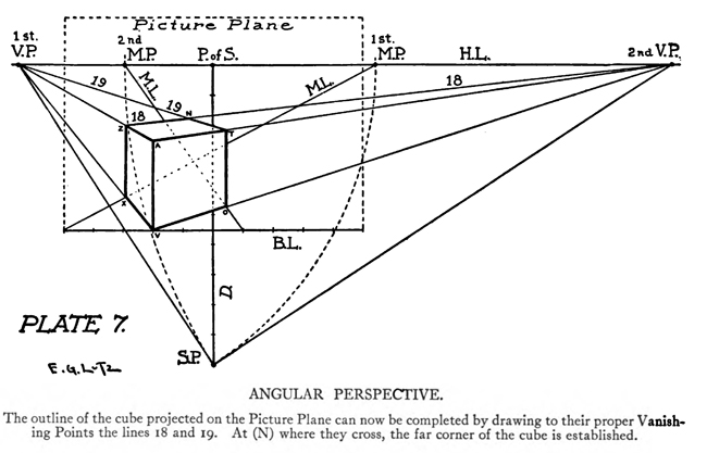
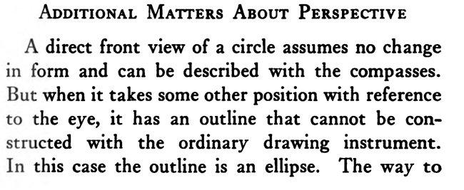
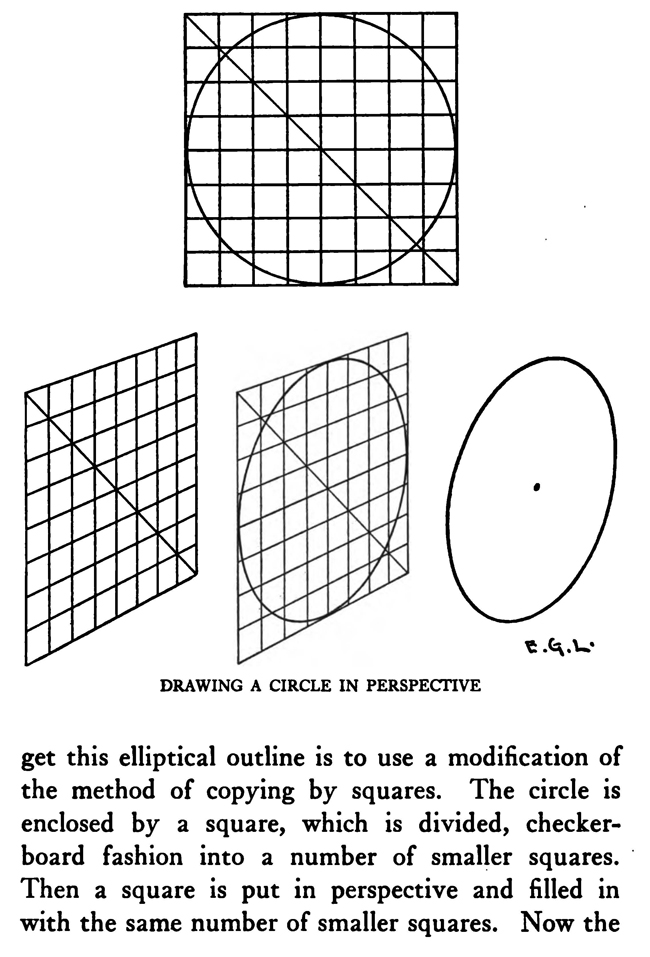
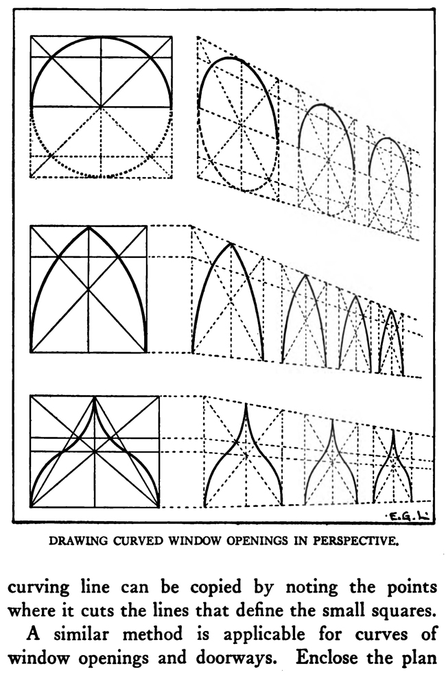
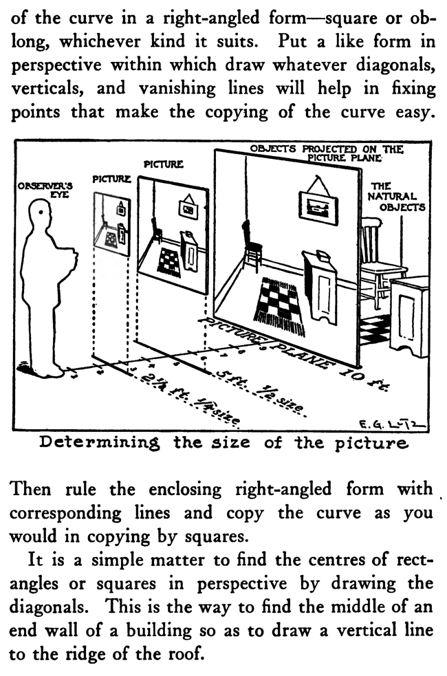
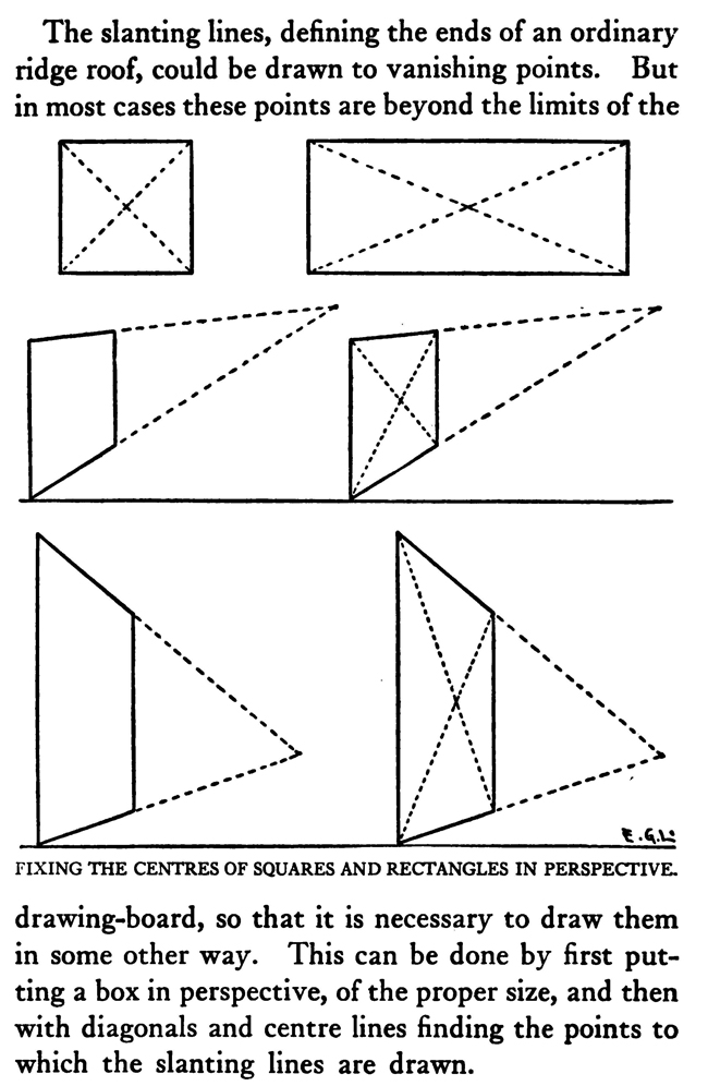
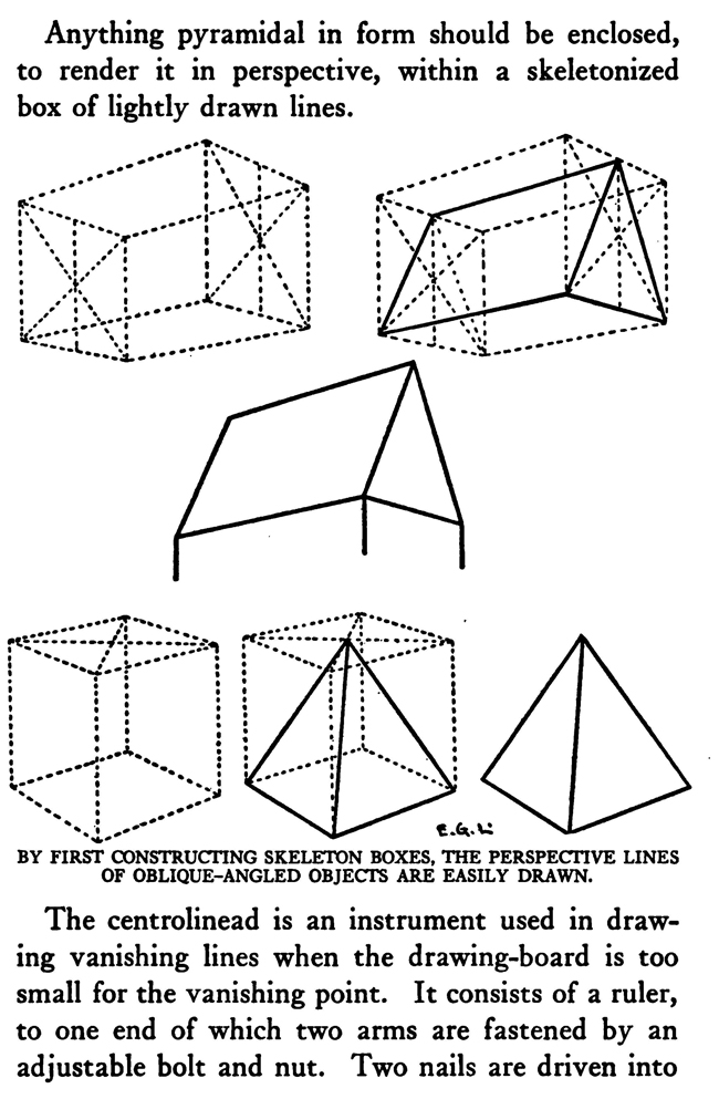
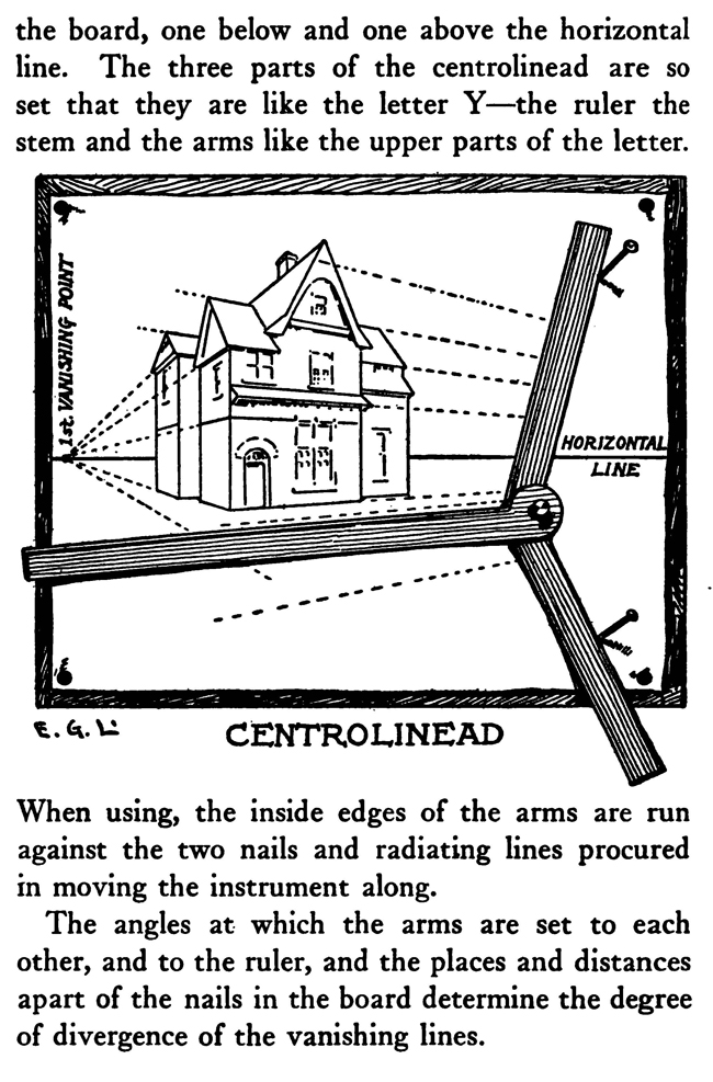
[The Text Above is Actually Images, so If You Need to Copy Text, You Can Do So Below] PERSPECTIVE/ MADE CLEARThe exemplification usually given in the introductory chapters of books on perspective is that of the window-pane on which the view outdoors is traced, or imagined as traced, perspectively. No simpler illustration than this can be given to make every one understand fully and vividly that that is the way the whole external world is perceived by the eye. The primitive artist did not depict things as he saw them; but as he palpably knew them. His knowledge of what things were, learned through sense and tangible apprehension, influenced him in his efforts at drawing. We look on his naive delineations, lacking perspective and light and shade, as nothing more than symbols. Perhaps to him, though, they were pictorially very realistic. The ancient Egyptians, if the pictures that they have left to us can be taken as a criterion, never realized that their eye was an optical instrument that reflected things perspectively. A pond bordered by plants and trees, drawn by an Egyptian artist was made as a map with the water conventionally shown in rows of zigzag lines. The bordering trees and plants looked as if they had been flattened out and pointed in the four directions of the compass. The two figures in the picture were drawn totally out of proportion to the rest of the composition. To indicate that there were growing aquatic plants, lotos blossoms were merely placed about. All to our eyes very decorative and symbolic, but to the ancient artist a faithful representation, perhaps, of the objects and view. The human figure was drawn in rather a queer way by the artists of ancient Egypt. It would be something like this: the legs and part of the body in profile, the shoulders twisted around to a front view, then the face in profile and the eye carefully outlined as it is seen in a full face view—all showing that he did not attempt to portray the figure as his eyes reflected it photographically. It would be hard to say whether he worked in his quaint way through lack of technical skill, disinclination, or non-realization of how objects and scenes actually looked to his eyes. The character of the drawing in the Pompeian wall-paintings shows that the artists of those times were beginning to notice that if they wanted to produce the semblance of reality in picturing solid angular things they must have certain lines slant, either downward or upward. But they did not seem to grasp the idea of conforming consistently to fixed vanishing points in the directions of these slanting lines. Then, too, the drawings of some modern Oriental artists betray in their simplicity ignorance of the elements of perspective. They have slanting lines to define their buildings and straight-edged solid objects; but the respective slanting lines do not go to vanishing points. Now, perspective could be easily comprehended if the external world, instead of being thought of as solid and material—which fact our tactile and mental faculties constantly remind us of—is in imagination projected forward and outlined on an ideal plane directly before our eyes. Doing this, considering the natural object you wish to draw as merely traced out on a supposed plane before you, is the first lesson in the study of perspective. The black-and-white draftsman is interested mainly in linear perspective. Curvilinear perspective is used in planning cycloramas, and aerial perspective is of interest to the landscape-painter and does not bring the question of lines into use, but concerns itself with differences of the tints and colors in a general view as they vary from the fore-. ground to the distance. The study and consideration of it help the artist in rendering correctly effects of atmosphere, space, and distance. Perspective Of linear perspective there are two kinds: parallel and angular. In the simpler of these, parallel, all the horizontal lines that are at right angles to the central visual ray, or the line of vision, are shown parallel; and the lines which in nature go in the same direction as the line of vision, in a perspective rendering recede toward a point on the horizon directly before the spectator's eye. A familiar example is that of a floor marked off into square feet with the crosswise lines parallel to the horizon. A view of a huge checker-board placed on the floor with one edge directly before you would do to illustrate it. A FANCIFUL ANALOGYMost drawings requiring pictorial projection are made in angular perspective. In this method the principal object is placed in such a way that some corner or angle points toward the observer and the lines bounding its edges converge obliquely toward vanishing points. The best way to make perspective clear is to give a particular example and show the way of procedure from the beginning and carried through to the end. You will find, then, illustrated in these pages, seven plates with explanations of a simple problem in angular perspective. It will be advisable, though, that perspective terms first be studied. TERMS USED IN PERSPECTIVEHorizontal Line.—A line on a level with the observer's eye, not always apparent. Visible in a view of the sea or the open flat country. Point of Sight.—A point on the horizontal line opposite the observer's eye. In parallel perspective this is also the vanishing point. It is sometimes called the centre of vision, or the centre of the picture. Distance.—The line marked in the drawing as running from the point of sight to the station point, or observer's eye, and measuring the principal distance. It will here be spoken of as the distance or the line of distance. This line is at right angles to the horizontal line and equal in length to the base-line or the width of the picture. When shorter, that is, bringing the observer's eye closer, the result will be a rendering of the objects in sharp-angled or violent perspective. This line is called by some the vertical line, probably because it is a vertical line in the drawing. But this term seems misleading, as the line represents in actuality an imaginary level one; i. e., the line of vision from the observer's eye to the centre of vision or the point of sight. Station Point.—The position of the observer's eye opposite the point of sight, and at a distance from it equal to the width of the picture. This position of the station point makes the optic angle for viewing things a proper one; that is within sixty degrees. It will help in working out problems in perspective to think of the station point and the line of distance as not on the flat surface of the paper but jutting out toward you. The station point is only placed on the paper to use in establishing the positions of vanishing and measuring points. If there is no room below on the drawing-board, the station point can be placed above the horizontal line. Base-Line.—A line parallel to the horizontal line and below it at a distance equal to the height of the observer's eye. The base of the picture plane and the front line of the ground-plan meet at the baseline. In working to scale, measurements are marked on the base-line. It is sometimes called the ground line. Picture Plane.—An imaginary plane resting on the base-line. The horizontal line crosses it at the height of the observer's eye. The line distance meets it at the point of sight at right angles. The picture plane can be likened to a transparent screen to which the points of the view are brought forward by lines that centre, or focus, at the eye. In passing through this screen these lines leave their impress and produce a huge picture of the view. Vanishing Point.—A point to which converge—in a perspective drawing—lines which in nature are parallel to one another. For level lines the vanishing points will be found somewhere on the (level) horizontal line. Inclined lines have their vanishing points either above or below the horizontal line. Second Vanishing Point.—If the first vanishing point is known, the second can be found by drawing a line from the first vanishing point to the station point and from here, at a right angle, another line continued to the horizontal line. Where this line cuts the horizontal line marks the position of the second vanishing point. Note and remember : in picturing right-angled objects, the two lines joining the vanishing points by meeting at the station point always meet at a right angle. Measuring Point.—A point on the horizontal line to which a line is drawn from a measurement or a scale on the base-line. This line is called the measuring line. A measuring point is obtained by centering the compasses at a vanishing point and drawing an arc from the station point to, and cutting, the horizontal line. The measuring point so obtained is used for determining or fixing lengths on lines going to its particular vanishing-point. In parallel perspective the measuring point and the station point are equidistant from the point of sight. Measuring Line.—A line to the measuring point from a measurement on the base-line. Where it cuts its respective vanishing line it will determine, perspectively, the measurement. Vanishing Lines.—Parallel lines that, in a perspective projection, recede and converge to a vanishing-point. Scales and Measurements are marked on the baseline. if Vertical Scale can be erected on the base-line. Of the two kinds of linear perspective, parallel, generally speaking, is the less complicated. Anything can be presented according to its rules, although it is not always the most practical way of working. But the method is easily explained. Vertical measurements can be obtained in two ways:1. Draw perpendiculars to the base-line—A and B. The required height (3% ft.) is procured from the scale on the base-line, marked at the perpendiculars and vanishing lines run to the points wanted, where they will mark the required heights. 2. The required height (3% ft.) of that edge of the box resting on line C is found and marked off from this line C. the ground-plan are copied on the perspectively projected block of squares. This, however, gives you only outlines of things as they appear in a ground-plan. To get up-and-down dimensions vertical measurements are necessary. These in parallel perspective are obtained in two ways. Now, as the picture plane rests on the base-line, sizes marked on either would be the same. So any size wanted can be obtained from the scale on the base-line, set off on a vertical on the picture plane, and carried back; that is, beyond the picture plane—by converging lines to the vanishing-point, which point in parallel perspective is also the point of sight. The other method is to take measurements from the different horizontal lines beyond the base-line. For instance, if each of the horizontal divisions of the plan represents one foot, that can be divided into twelve inches. Then a desired height at any point can be established by erecting there a vertical line and marking the desired height from the scale of inches to be found on the particular horizontal line on which it rests. Angular perspective is demonstrated by the seven plates included in this chapter. They show, step by step, how to picture a cube in perspective. It will help in working out the problem in first marking a floor with the specifications of the problem. Draw Horizontal Line 2, and at right angles to it line 2 Mark Point of Sight, and below, at to ft., the Station Point. This determines the line of Distance. The observer's eye is 554 ft. high, so at this distance draw below the Base-Line 3, parallel to the Horizontal Line. Mark a scale of feet on the Base-Line. Indicate lightly the limits of the Picture Plane 4, make it the width of the Base-Line and any desired height within to ft. From the point 2 ft. to the left of the centre, where the front corner of the cube touches the Base-Line, sketch line 5, the receding edge, next the floor, of the left side of the cube. ANGULAR PERSPECTIVE.Line 5, which has just been drawn, is continued until it cuts the Horizontal Line. This marks the position of the tat Vanishing Point. The next step shows how to get the 2nd Vanishing Point. From the tat Vanishing Point draw line 6, to the Station Point, and from here at a right angle draw line 7, which continue until it cuts the Horizontal Line. This marks the position of the 2nd Vanishing Point. From here draw Vanishing Line 8, giving the receding angle of the other edge of the cube next the floor. The length of the receding edges of the cube can be exactly fixed. To do this you must first find the Measuring Points. With the 1st Vanishing Point as a centre, draw arc 9 from the Station Point to and cutting the Horizontal Line. This gives the Measuring Point for lines running to the 1st Vanishing Point. The other Measuring Point is found by drawing arc 10 from the 2nd Vanishing Point as a centre to and cutting the Horizontal Line. The scale of feet which you have marked on the Base-Line is now put to use. The edges of the cube are 3 ft. long, so mark 3 ft. to the left of the point where the corner of the cube touches the Base-Line. From this 3-ft. mark draw line 11 to the 1st Measuring Point. Where line it cuts lines at (X) fixes the length of that edge of the cube. The length of the other edge is ascertained by drawing in a similar way line 12 from a 3-ft. mark to the right, to the 2nd Measuring Point. These lines, 11 and 12, are Measuring Lines. Line 13, which is drawn next, represents the front edge of the cube. It is exactly even with the surface of the Picture Plane, and the scale marked on it would be the same as that on the Base-Line. So mark on line 13 the length of that edge of the cube; namely, 3 ft. You now have three edges of the cube established as they appear in perspective. ADDITIONAL MATTERS ABOUT PERSPECTIVEA direct front view of a circle assumes no change in form and can be described with the compasses. But when it takes some other position with reference to the eye, it has an outline that cannot be constructed with the ordinary drawing instrument. In this case the outline is an ellipse. The way to get this elliptical outline is to use a modification of the method of copying by squares. The circle is enclosed by a square, which is divided, checkerboard fashion into a number of smaller squares. Then a square is put in perspective and filled in with the same number of smaller squares. Now the curving line can be copied by noting the points where it cuts the lines that define the small squares. A similar method is applicable for curves of window openings and doorways. Enclose the plan of the curve in a right-angled form— square or oblong, whichever kind it suits. Put a like form in perspective within which draw whatever diagonals, verticals, and vanishing lines will help in fixing points that make the copying of the curve easy. Then rule the enclosing right-angled form with corresponding lines and copy the curve as you would in copying by squares. It is a simple matter to find the centers of rectangles or squares in perspective by drawing the diagonals. This is the way to find the middle of an end wall of a building so as to draw a vertical line to the ridge of the roof. The slanting lines, defining the ends of an ordinary ridge roof, could be drawn to vanishing points. But in most cases these points are beyond the limits of the drawing-board, so that it is necessary to draw them in some other way. This can be done by first putting a box in perspective, of the proper size, and then with diagonals and centre lines finding the points to which the slanting lines are drawn. Anything pyramidal in form should be enclosed, to render it in perspective, within a skeletonized box of lightly drawn lines. The centerline is an instrument used in drawing vanishing lines when the drawing-board is too small for the vanishing point. It consists of a ruler, to one end of which two arms are fastened by an adjustable bolt and nut. Two nails are driven into the board, one below and one above the horizontal line. The three parts of the centerline are so set that they are like the letter Y—the ruler the stem and the arms like the upper parts of the letter. When using, the inside edges of the arms are run against the two nails and radiating lines procured in moving the instrument along. The angles at which the arms are set to each other, and to the ruler, and the places and distances apart of the nails in the board determine the degree of divergence of the vanishing lines. |


Privacy Policy ...... Contact Us