The perspective facts involved in drawing interiors are similar to those already demonstrated in exterior subjects. The principal difference being in the observer’s position: in one case he is outside, in the other, inside.
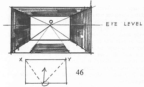
In Figure 46 we see that the converging lines of all foreshortened surfaces—walls, floors, ceiling, rug and any furniture that may line up with the side walls—meet at 0, a point on the level of the observer’s eye, in the center of the rear wall; the assumption being that the spectator stands in the center of the room and directs his gaze in the general direction of O. Hence the room’s corners, X and Y, are equidistant from him and should appear of equal height. The rear wall, therefore, should be represented as a perfect rectangle.
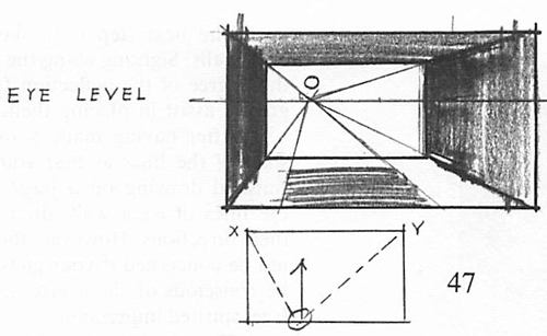
In Figure 47 the spectator has moved to the left side of the room; therefore, assuming that he directs his gaze parallel with the receding walls, the vanishing point moves to the left, as shown. However, if he directs his eyes in the general area of the Y corner we have to make a new diagram to represent the changed viewpoint.
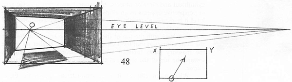
The Y corner, being farthest from him, would appear perspectively shorter than the X corner, thus creating an effect, theoretically, like that of Figure 48, in which the lines of the side walls converge, as in Figure 47, but those of the rear wall and all objects parallel with it (the rug) converge as shown. This gives what may appropriately be termed two-point perspective, being contrary to the way the room actually looks to the eye of a person in the described circumstances. It does represent the way the room would be seen by the camera lens, which often differs radically from the human eye. The person taking the position described in Figure 48, and looking slightly toward the Y corner would see the left wall but dimly in the periphery of his vision. This conclusion can readily be proved by experiment.
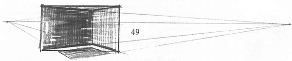
Figure 49 represents what might be called normal appearance, the left wall not being seen at all.
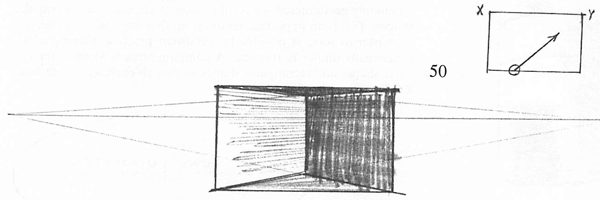
When the direction of sight aims directly at the corner, as in Figure 50, there is equal foreshortening and convergence of both walls. This is the viewpoint in the sketch of the room interior [Figure 45].
Although, as previously stated, the appearance of a room represented by the diagram in Figure 48 is contrary to normal vision, it is one that has practical value inasmuch as it is more inclusive than Figure 49. It is commonly used by architects and interior decorators for obvious reasons. In this kind of treatment there can be distorted effects when too much of the room’s depth is included as in Figure 48, where the rug, brought into the near foreground, takes on an unnaturally acute angle. However, in this day of close-up photography we have become used to all kinds of distortions which formerly were not tolerated.
When sketching interiors it is advisable first to ascertain the height of the eye-level. The chances are that in your subject there will be some horizontal lines of both side walls that are on your eye-level; that is, they actually will be horizontal in your drawing. In the pencil sketch [Figure 45] the eye-level is the bottom edge of the picture behind the lamp. The suggestion for sighting along the top edge of your drawing board can be applied profitably here.
The next step is to sketch in the ceiling and floor lines of both walls. Sighting along the top edge of your board and estimating the degree of the deflection from the horizontal of these lines will greatly assist in placing them properly.
After having made your interior drawing, by estimating the slant of the lines as best you can, it will be instructive to lay the finished drawing on a large table or the floor and, by extending the lines of each wall, discover how accurately you have judged their directions. However, though it is desirable to be accurate, do not be concerned if your guess is only approximate; few people will be conscious of slight errors. More important than exactitude is a free, spirited impression.
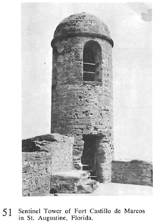
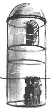
The photograph of the Sentinel Tower [Figure 51] serves to demonstrate one of the essential perspective facts dealing with cylindrical and circular objects. Everyone knows that a circle seen in perspective appears as an ellipse. When held horizontally at eye-level it is merely a straight line. The photographer evidently stood upon something slightly above the pavement because the camera was on a level with the top of the doorway. We know this because the stone courses at that level show a straight line. Higher up we see the masonry joints forming ever wider (front to back) ellipses toward the top of the tower; at the pavement level, a very narrow ellipse.
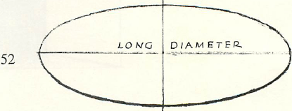
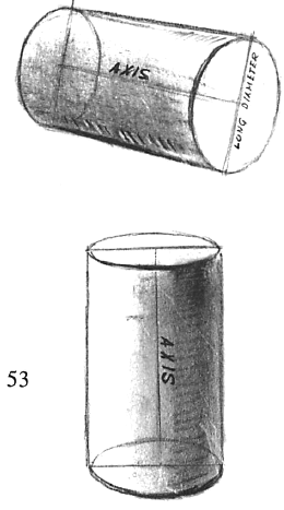
What is an ellipse? It is a symmetrical, geometric figure [Figure 52], not an oval. When folded on either the long or short diameter, each folded half lies exactly on its corresponding half. That is not a perfect geometric definition. The dictionary is more specific. However the practical way to acquire the correct concept of an ellipse is to make many tracings of ellipses from photographs. The camera gives correct perspective results in this case, although it does not tell the truth in many other situations. In practicing ellipses, use a free arm movement. It is almost impossible to draw a good ellipse with finger movement.
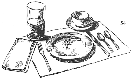
The table service sketch [Figure 54] presents a situation that is commonly encountered—a combination of circular and rectangular shapes. This is an important relationship that the student should try to master as soon as possible by persistent practice drawing of arrangements similar to this one. A common error is to draw the circular shapes and rectangular shapes as though each were seen from a different eye-level.
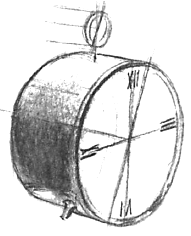
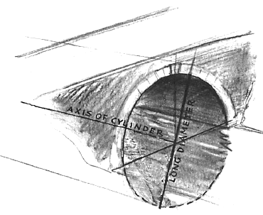
Another important perspective fact is demonstrated in Figure 53. The long diameter of the ellipse always appears at right angles to the axis of a cylinder whatever the cylinder’s position. Thus, when the cylinder is lying on its side, the long diameter of the elliptical end is not a vertical line, but is slanted at a 45-degree angle to the cylinder’s axis as shown. This can be puzzling at first because the long diameter of the ellipse may be confused with a structural line on the circle’s face such as a line through the numerals VI and XII on a clock face. In a circle, that structural line is always vertical while the axis of the ellipse is a variable, viewpoint—the axis of the ellipse being an imaginary line of perspective appearance. In this connection refer again to Figure 32, the drawing by Thomas Rowlandson and the diagram underneath it. Note that (in the diagram) the wheels are visualized as the ends of cylinders and that the ellipses which represent them in perspective are constructed on long diameters which are at right angles to the axes lines of the cylinders. It is usually helpful when drawing circles in perspective to visualize them as the ends of imaginary cylinders. Thus the arch of the bridge can be thought of as lying upon a huge cylinder.
Technorati Tags: perspective drawing, drawing in perspective, guide to perspective drawing, perspective drawing lessons, perspective drawing tutorials, one point perspective, two point perspective, 1 point perspective, 2 point perspective, perspective, cylinders, drawing lessons, drawing tutorials
Today I'll show you how to draw a cute kawaii bunny and kawaii carrot character…
Today I will show you how to draw a cartoon Viking ship. I have broken…
Today I'll show you how to draw Rick from the Rick and Morty cartoon tv…
Today I'll show you how to draw Morty from the Rick and Morty cartoon tv…
Today I'll show you how to draw the spunky little rabbit, Kuromi, from My Melody…
Today I'll show you how to draw this cute "bean duck" that I found on…
View Comments
Very good webiste. This is very helpful for all seo. Thanks!
execellent